Heading into the design cycle, the Aerodynamics subsystem was faced with overcoming the challenge of a reduced rules box defined by track width and wheel base that the aero package could reside in. To regain this downforce deficit, our team had to create a more potent package utilizing vortex generating footplates, closely studying fullcar flow to rear wing, repositioning wings, and other design modifications.
To quantify aerodynamic development to real-life competition gains, our team utilizes Lapsim, our in-house (Vehicle Dynamics subsystem-developed) event-simulating program to derive our subsystems point trade off equation and ultimately drive aerodynamic design.

The center of pressure (CP) of the car is a critical spec that our team makes every effort to hit year after year. Driver feedback from B19 suggested that the car tended to oversteer at high speeds, so our subsystem worked together with Vehicle Dynamics (VD) to quantify a model that relates understeer gradient (relative grip between front and rear wheels) to CP placement.


The primary goals of the front wing were to increase downforce generation per unit area to make up for losses in our smaller usable rules box. Furthermore, the front wing was painstakingly designed to act as a reactionary measure to a fully optimized (but still limiting factor in terms of downforce generation) rear wing, to properly place the fullcar CP.
The footplates above generate and contain an artificial sealing vortex to more effectively maintain the extreme low pressure region underneath the wing, while simultaneously creating downforce in of itself. Typically, viscous flow tends to change direction as it is pulled down beneath the endplate by the suction side of the wing. But, adding footplates reduces the downwards spillage from the viscous layer on the outer surface of the endplates by creating a constriction of area between these regions. This causes an initial acceleration of the flow, therefore causing the formation of a vortex in the cylindrical area and ultimately lowering the pressure.
An adverse pressure gradient exists from directly beneath the footplate to just inboard beneath the front wing, resulting in recirculation pulling the flow back towards the inside surface of the endplate. Without a footplate, this vortex would naturally form from shear layer separation on the inboard face of the endplate. But, because of the adverse pressure gradient between these areas, this naturally occurring vortex strengthens, further increasing the pressure differential between the upper and lower wing surfaces.
Also, to account for the natural growth of vortices, our team simulated an expanding radius C-channel to attempt to contain this vortex as long as possible to maximize downforce. At approximately 12" chord, the low pressure vortex forms. But as the chord approaches 17" this same vortex is growing to fill the larger radius C-Channel. When we didn't expand the radius of the C-Channel, this vortex would begin to spill out at around this distance, lowering downforce generation.

Our goal for B21 was to absolutely maximize rear wing downforce production while simultaneously creating a lighter package.
Even though the rear wing coefficient of lift * area (CLA) saw an 11 percent boost over the previous year, our coefficient of drag * area (CDA) unfortunately saw a 30 percent boost, as well. But, since the B20 wing has a much smaller frontal area than the B19 wing we still saw an overall reduction in drag. Similarly to the front wing, due to the wheels track length shrinking, the rear wing also experienced a rules box squeeze.
This smaller frontal area is due to the reduction in height of the multi element stack, with the intent of bringing the leading edge of the mainplane as high into free stream as possible. Using a higher camber profile such as the MSHD airfoil allows us to produce greater lift at lower mainplane angles of attack.

In the plot above, one thing that stood out to us was that for angles of attack from 0 to 5 degrees, the CL for MSHD is much higher than its competitors that we have used previously. This was the basis for us achieve similar downforce figures with a wing that occupies less Z volume.
In addition to shortening the stack of elements, we simultaneously reclined the driver,
lowering her or his helmet as much as possible. In the table on the left on the image below, there are a few driver angles we simulated. The bottom row is a report of potential performance utilized in a "full car sense" defined by the half car simulated downforce divided by the free stream downforce with the same rear wing.
lowering her or his helmet as much as possible. In the table on the left on the image below, there are a few driver angles we simulated. The bottom row is a report of potential performance utilized in a "full car sense" defined by the half car simulated downforce divided by the free stream downforce with the same rear wing.
As we can see the high driver angle and low leading edge of the B19 wing created only 59% of the possible downforce in free stream. Meanwhile, this year's wing produced 84 percent of its original downforce, ultimately producing just 6% less downforce in half car than last years much larger and heavier wing.

With all of this in mind we ultimately ended up with a rear wing that was 4 pounds lighter than the previous year, much smaller, and much more potent in terms of downforce production.

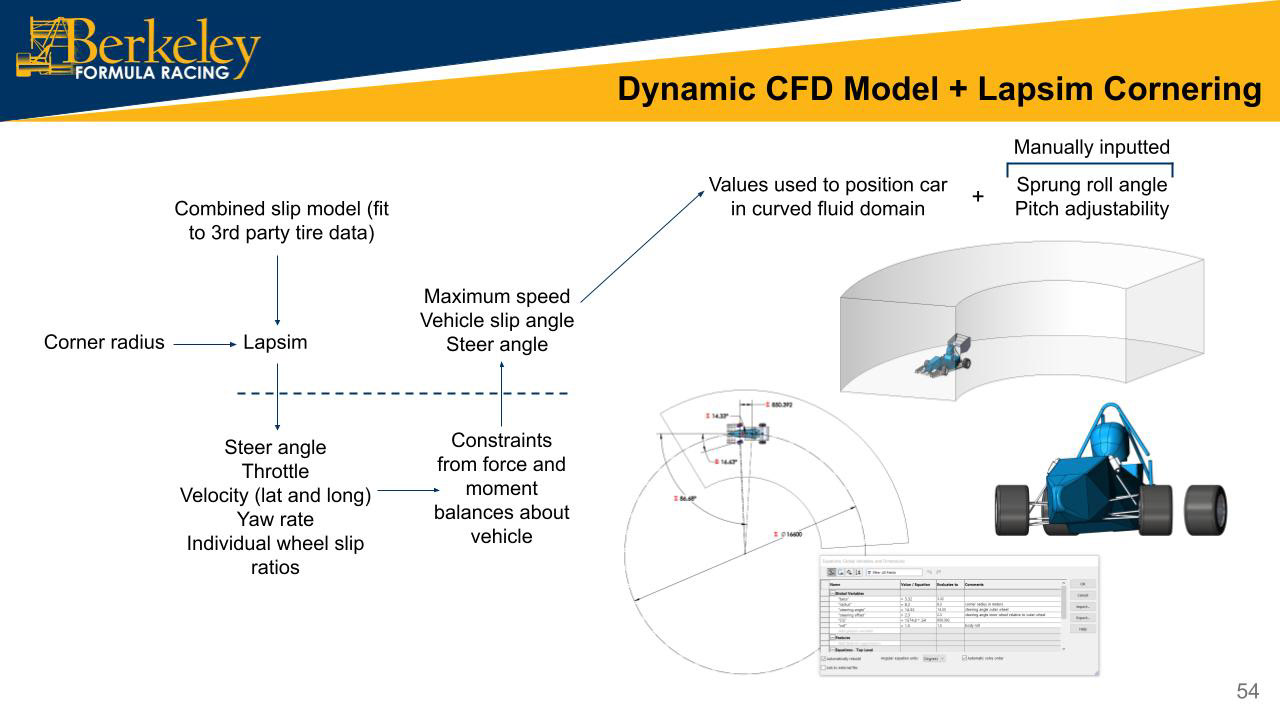
Designs were then evaluated through equation-parameterized full-car simulation, with straight and curved fluid domains, moving ground, rotating wheels, front wheel beta angle, chassis/aero package yaw, roll and pitch adjustability. Much of the design work was performed in the dynamic full-car simulations to create an aerodynamically robust package that functions as intended throughout all expected racing conditions.
None of this is possible though without tight integration to Lapsim, as detailed in the slide below.


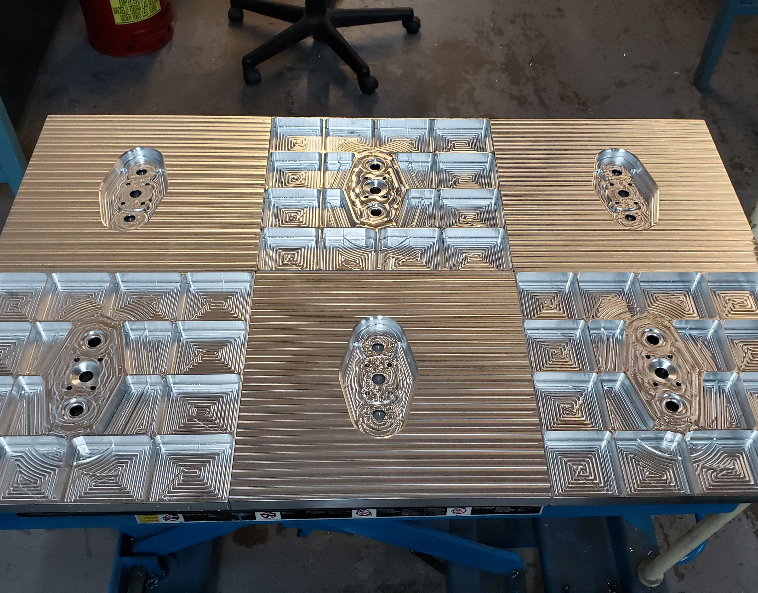
The overall package weight was reduced significantly through subsystem-wide material and geometry optimizations such as trussed and pocketed aluminum internal ribs, polycarbonate flap element ribs, wing skin thicknesses, simplified mounting truss geometry, and varying density aluminum honeycomb and nomex sandwich panels.
The total weight of the front wing mounting and internal rib structures reduced by 21.6%, from 1.85 lbs in B19 to 1.45 lbs in B20 while the rear wing mounting and internal rib structures reduced by 11.7%, from 2.05 lbs to 1.81 lbs total. Finally, the carbon fiber assembly of the rear wing is lighter due to the reduced size of the package.


The entire aerodynamics package weighs 22 pounds, which combined with the package CLA and CDA equates to a dynamic points gain of +26 points. Overall, the fullcar B20 aerodynamics package produces 764 N of downforce and 341 N of drag at 80 kph. This equates to a CLA of 2.52 m^2 and a CDA of 1.12 m^2 at a center of pressure of 61% of wheelbase.